- Oferta
 Kosmetyki
 Farmacja i suplementy diety
 Dodatki do żywności
 Kleje przemysłowe
 Guma i tworzywa sztuczne
 Maszyny i materiały do elektroniki
- Maszyny do Lutowania
- Maszyny do Testowania Elektroniki
- Maszyny do Mycia PCB
- Maszyny do Montażu SMD
- Maszyny do Dozowania i lakierowania elektroniki
- Maszyny do Automatyzacji
- Maszyny do Depanelizacji PCB
- Maszyny Specjalne
- Liczarki komponentów SMD
- Materiały do Lutowania
- Materiały do Mycia PCB ESD
- Materiały do Zabezpieczania Elektroniki
 Środki smarne
 Chemia gospodarcza i agrochemia
 Oczyszczanie ścieków przemysłowych
 Powłoki malarskie i kleje
- Aktualności
- O nas
- Współpraca
- Kontakt
Roboty SCARA
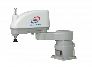 Roboty SCARA (Selective Compliance Assembly Robot Arm) to specjalistyczne, wysoko wydajne urządzenia do zastosowań przemysłowych, które łączą w sobie szybkość, precyzję i niezawodność. Wyjątkowa budowa i innowacyjne rozwiązania sprawiają, że roboty SCARA doskonale nadają się do szerokiego spektrum zastosowań - od montażu delikatnych komponentów po powtarzalne procesy pakowania i sortowania.
Roboty Scara to innowacyjne, precyzyjne urządzenia zaprojektowane z myślą o automatyzacji procesów przemysłowych. Nasza oferta obejmuje nowoczesne roboty, które charakteryzują się:
- Wysoką precyzją i niezawodnością: Idealne do zadań wymagających dokładności, takich jak montaż, spawanie czy malowanie.
- Łatwością integracji: Elastyczne rozwiązania pozwalają na szybkie wdrożenie robotów do istniejących linii produkcyjnych.
- Zaawansowaną technologią: Wyposażone w nowoczesne systemy sterowania, zapewniają optymalną wydajność i bezpieczeństwo pracy.
- Optymalizacją kosztów: Automatyzacja procesów pozwala na redukcję kosztów operacyjnych oraz zwiększenie efektywności produkcji.
Zapraszamy do zapoznania się z naszą ofertą robotów Scara firmy Janome Industrial Equipment – rozwiązaniem, które pomoże Twojej firmie osiągnąć nowy poziom produkcji i konkurencyjności.
C.H. Erbslöh Polska Sp. z o.o.
jest profesjonalnym doradcą technologicznym i dystrybutorem Robotów Scara producenta
Janome Industrial Equipment oraz firmy Elmotec

Materiały do elektroniki
|
Jerzy Ziółkowski +48 606-893-910 |
Rafał Przegaliński +48 605-548-484 |
Maszyny i urządzenia
|
Aleksander Jaświec +48 603-411-677 |
Tomasz Bińkowski +48 609-743-474 |